LM2596 Adjustable Step-down Module with Voltmeter Display - DC-DC Converter


0 out of 5 stars
No review yetReady stock
NaN
As low as NaN
Worldwide shipping
Seller: Worldswa Shenzhen
ID: MV-22041694U347
Weight: 0.05 kg
| Qty | Price | Discount |
|---|---|---|
| 1 | NaN | |
| 3 | NaN | -2.4% |
| 5 | NaN | -4.8% |
| 10 | NaN | -7.1% |
Product details
Description
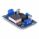
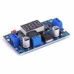
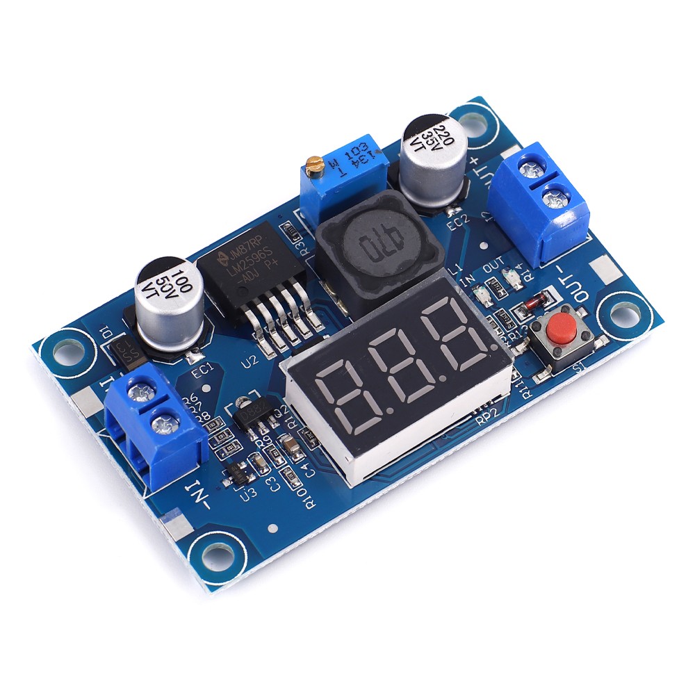
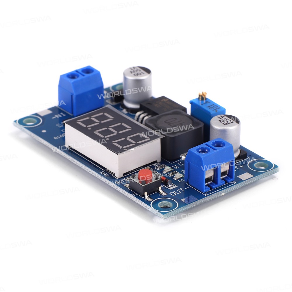
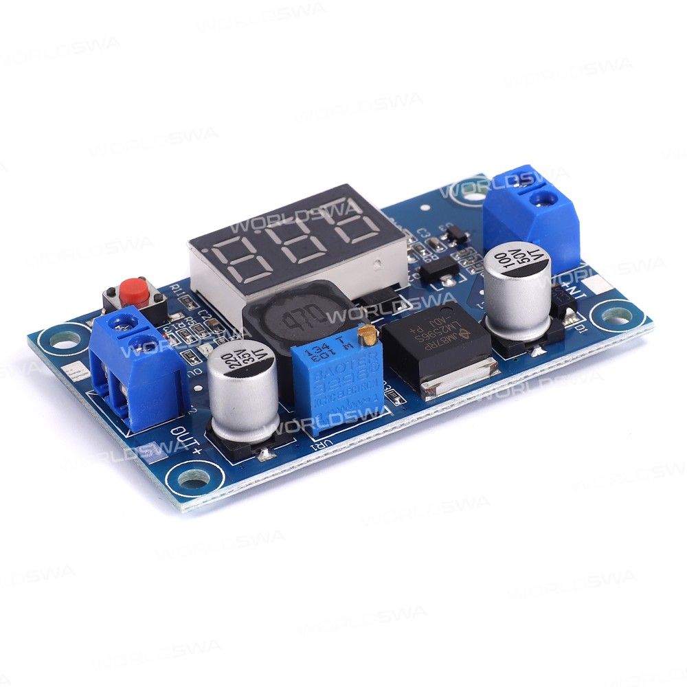
DC-DC Step-down Power Module with Digital Display
This module can be applied to fields in the input voltage is higher than the step-down output voltage, such as batteries, power transformers, DIY adjustable power supply, 24V Car T of the power equipment industry buck, 12V switch 3.3V, 12V switch 5V, 24V switch 5V, 24V switch 12V, 36V 24V turn and so on.
Features:
- Name: DC-DC Step-down Power Module with Digital Display
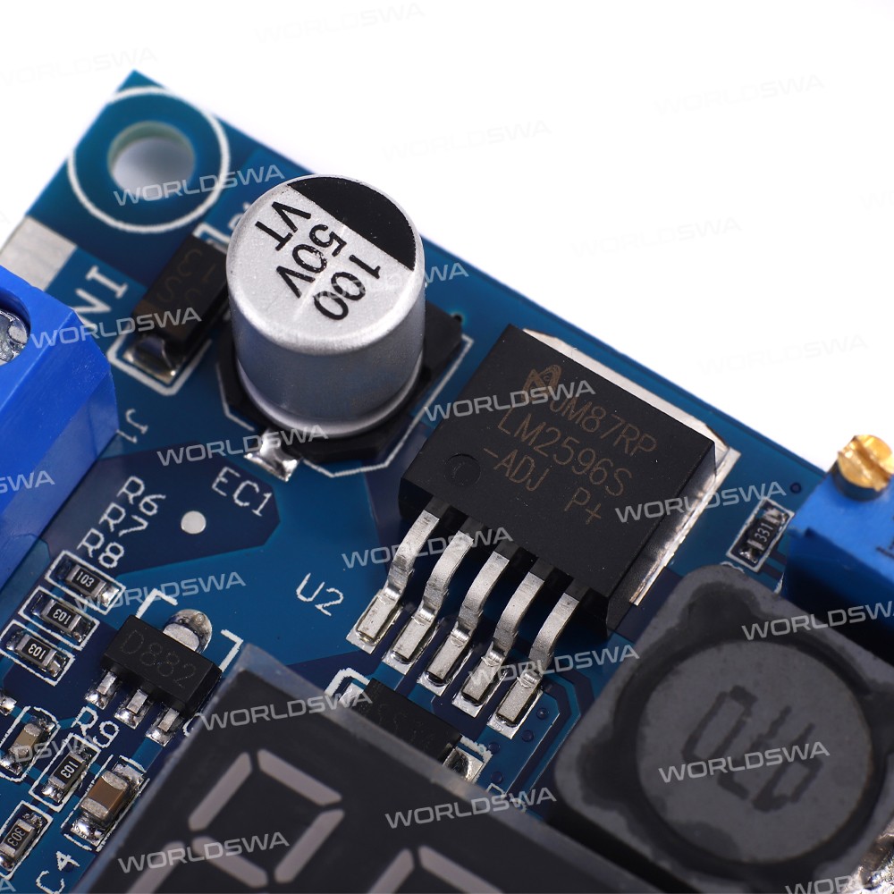
- Model: LM2596
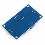
- Product size: 66*36*14mm
- Colors: Blue
- Weight: 23g
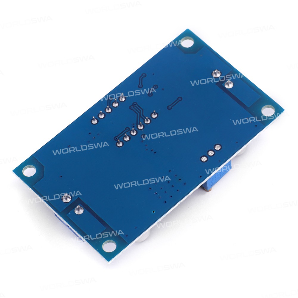
- Materials: FR4 + Electronic components
- Summary:** High-performance step-down converter with digital display, featuring high conversion efficiency, reverse polarity protection, and adjustable output voltage range.
Voltage Meter and Adjustment:
- A voltage meter and voltmeter display self-calibration
- Uses a more advanced microprocessor voltage voltmeter error ± 0.05V, Range 0 ~ 40V. (To ensure accuracy voltmeter, make sure the input voltage of 4.5V and above)
- Touch of a button to switch the input or output voltage measurements and has a light show which is being measured voltages, and save the settings, even the power off and then on
Specifications:
- Input Voltage: 4.5~ 40V. (Input voltage must be higher than the output voltage of 1.5v or more)
- Adjustable Output Voltage: 1.25V ~ 37V continuously adjustable. (Input voltage must be higher than the output voltage of 1.5V)
- Output Current: 3A, recommendations within 2.0A use, and high current needed to enhance heat dissipation
- Output Power: 20W, 15W, please enhance heat dissipation over
- Conversion Efficiency:** Average 88% (efficiency and the input and output voltage, current, pressure-related)
- Reverse Polarity Protection:** Yes, reverse polarity does not burn
Usage:
- The onboard voltage table shows the output voltage, long press on the right button for 2 seconds after the release, voltmeter, and the output voltage indicator "OUT" synchronous flashing, this time into an output voltage adjustment mode
- Similarly, the voltmeter shows when the input voltage, long-press the Right button 2 seconds after the release, voltmeter, and an input voltage indicator "IN" synchronous flashing, then enter the adjustment mode input voltage
- Touch the right side of the button, the voltage increases one unit, touch the left button, the voltage reduction unit; because the voltage is less than the value of a unit of 0.1V, so you need to press the 1-5 times in a row to see the voltmeter change of 0.1V, concrete continuous button several times depending on the voltage value currently displayed, the current display higher the voltage, the fewer the number of presses
- When the voltage is adjusted, long press on the right button for 2 seconds after the release, then you can exit the voltage calibration mode, all parameters are set to automatically power down to save
- Tips: this way you only need to adjust the calibration once to get precise voltage values over the entire voltage range, this feature is designed to meet your requirements and design a higher accuracy, and ease of use
Notes:
- When the module output voltage can not be adjusted, the output voltage is always equal to the input voltage. Please adjust the potentiometer counterclockwise 20 laps or more. (Let potentiometer against your chest, counterclockwise turn boost) .
- Input voltage must be higher than the output voltage of 1.5v or more high current or high power needed to enhance heat dissipationcreen
Customer reviews
0.0/ 5.0
0
0
0
0
0